

Description
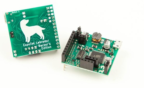
Labrador is an all-in-one tool for electronics students, makers and hobbyists. Just plug your Labrador board into a PC (Windows/Mac/Linux), Raspberry Pi or Android device via a MicroUSB cable, load up the software and you instantly have the following engineering tools at your disposal:
- Oscilloscope (2 channel, 750ksps)
- Arbitrary Waveform Generator (2 channel, 1MSPS per channel)
- Power Supply (4.5 to 12V, 0.75W max output, with closed-loop feedback)
- Logic Analyzer (2 channel, 3MSPS per channel, with serial decoding)
- Multimeter (V/I/R/C)
Oh, and did I mention that both hardware and software are 100% open-source?

Software:
The development of Labrador took more than 2.5 years to complete, and most of this effort was put towards the software interface. Everything was been designed from the ground up to be simple to use for beginners, while retaining features that more experienced engineers could take use of.
There’s a fully featured 2-channel DAQ mode with variable sample rate, CSV export, signal averaging and offline playback, but it’s placed up in the menus rather than the main screen. Design decisions like this make Labrador suitable for makers and engineers of all skill levels.
The oscilloscope, especially, was redesigned from first principles to take advantage of the host PC’s immense processing power and memory. Every sample captured by the board’s ADC is sent over USB and buffered by the PC software, allowing you to view minute-long streams at a 60Hz refresh rate without a single gap in the waveform.
The controls were designed with keyboard and mouse (or trackpad) in mind. Note the lack of virtual knobs and dials in the screenshot below. All of this makes designing and debugging your circuits easier than ever – yes, even compared to products from the likes of Tektronix and NI.
The Desktop software interface can be downloaded from GitHub Releases.
The Android software can be downloaded from Google Play.
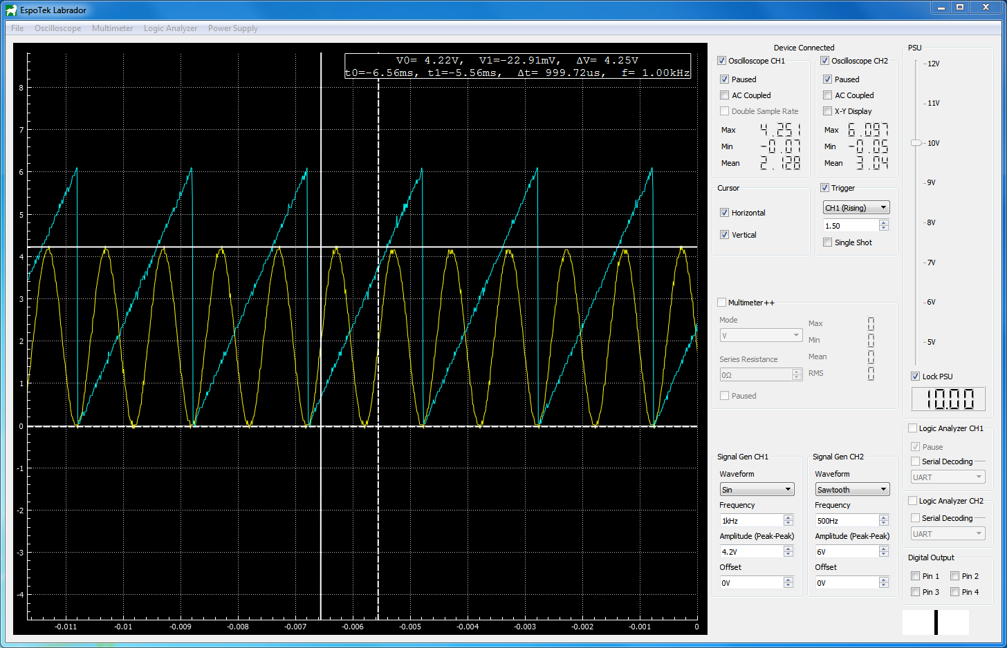
Above is an example of what the software interface looks like. Here, the signal generators are generating two different waveforms (sine and sawtooth), while the oscilloscope displays the two waveforms and the horizontal and vertical cursors measure the sine wave. Of course, if you’re a beginner, you don’t need to be doing all of that at the same time!
Support and Documentation:
Labrador users have access to the best support possible: a direct email link to the product developer. If you have any issues or suggestions, email [email protected] and I’ll do what I can to help; be it getting the software running on an unsupported OS, adding in a feature you’d like or just getting your board up and running.
In addition to this, community support and discussion is available at the GitHub Issues Page.
Full documentation (including pinout and a tutorial for beginners) for the hardware and software is available at the GitHub Wiki Page.
Full specs:
| Oscilloscope | Sample Rate | 750ksps (shared) |
| Bits per Sample | 8, 12¹ | |
| Bandwidth | ~100kHz² | |
| Input Voltage Range | -20V to +20V | |
| Input Impedance | 1 MΩ | |
| No. of Channels | 2 | |
| Coupling | AC/DC | |
| Arbitrary Waveform Generator | Waveform types | Sin, Square, Triangle, Sawtooth, Arbitrary |
| Sample Rate | 1Msps | |
| Sample Depth | 512 samples per channel | |
| Output voltage range | 0.15V to 9.5V | |
| Bits per Sample | 8 | |
| Max. Current | 10mA³ | |
| Output Resistance | 50Ω | |
| No. of Channels | 2 | |
| Variable Power Supply | Voltage Range | 4.5V to 12V |
| Max. Power | 0.75W | |
| No. of Outputs | 1 | |
| Source Impedance | Negligible⁴ | |
| Ripple Voltage | +-300mV%@10V 10mA, +-700mV%@10V 100mA | |
| Logic Analyzer | Sample Rate | 3Msps per channel |
| Supported voltage | 3.3V, 5V, 12V | |
| No. of Channels | 2 | |
| Digital Output | Voltage | 3.3V |
| Source Impedance | 50Ω | |
| Multimeter⁵ | Input Impedance | 1MΩ |
| Measured Parameters | V, I, R, C | |
| Voltage Range | -20V to +20V | |
| Current Range | 100uA to 10A | |
| Resistance Range | 1 ohm to 100k | |
| Capacitance Range | 10nf to 1mf | |
| Supported Platforms | Windows | Windows 7, 8, 8.1 or 10. 32 and 64-bit supported. |
| MacOS | 10.10 (Yosemite) or later | |
| Linux | Ubuntu 14.04 or later (or similar). 32 and 64-bit supported. | |
| Android | Version 4.1 or later |
¹ – 12-bit sampling is available at 375ksps, single-channel only.
² – This figure is an approximate “maximum detectable frequency” dictated by the sample rate.
³ – This figure is for source current. Current is sunk partially into the opamp driving the signal gen and partially into a 1k resistor. Thus, maximum sink current can be calculated by dividing the output voltage by 1k and adding 50µA. This configuration was chosen so that capacitive loads could be driven without significant nonlinearities. In simpler terms, this means that if you’re trying to drive current into the waveform generator through use of an external current source, then the maximum current that the waveform generator can handle is reduced. (This is not something that would be an issue for most people.)
⁴ – The Power Supply is controlled by a closed-loop feedback loop that ensures the DC voltage across output remains constant. Thus, it has nonlinear elements, but can still be approximated by a Thévenin circuit with Vth = Vo and Rth = 0.
⁵ – Multimeter ranges vary with reference resistor used.
Sebastain Bunnik –
Great product should definitely buy it, especially if you’re a student.
Joe –
I ordered this great device and had some trouble getting started. I emailed Chris and he replied promptly! His advice was great and he was so helpful with my issues. I’ve never had such good support in the tech world. I am now up and running and enjoying the learning experience. I’m an old guy and my background is electronics … I would encourage anyone who enjoys electronics and wants to learn to order one of these bad boys– it is sitting proudly on my work bench and I’m exploring all of the applications it has to offer. Much thanks to Chris for his immediate attention.
David Duval (verified owner) –
I received my Labrador this week, and so far it has been really fun and enjoyable to use! Setup was quick and straightforward in Arch linux.
Svjatoslav Agejenko –
Best functionality for money. Awesome for learning. Cannot wait for similar but upgraded version. For instance it would be great if all features could be used at the same time. Also it would be awesome to be able to have full LCR tester without external components. More channels and higher analog sampling rate for oscilloscope would be very welcome.
Peter (verified owner) –
I am a hobbyist and purchased this more for curiosity than I have a burning need for one. I must say I am most pleased with the hardware and the software. From having seen and never used an oscilloscope before, I had the Labrador Board hooked up, and software up on my MacBook Pro, and displaying signals in about 6 hours. I can’t wait to read some more and find some uses for this wonderful combination.
Matt (verified owner) –
I’ve been looking around for a simple oscilloscope to experiment with electronics. Everything out there was super expensive. This board gives me the perfect amount of functionality for my needs and you can’t beat the price!
Manolis –
This little guy is perfect! I have started learning electronics as a hobby and this is a huge leap in being able to understand, troubleshoot, visualize circuit relevant issues and more. What a price! The seller is very eager to help! It is perfect for students and hobbyists!! Recommend 101%.
Hampton –
Yeah, if you’re thinking about it, just buy it. Does it compete with a $1500 scope? No. But it’s absolutely, hands-down the best way to get into electronics measurement in a simple way, without breaking the bank. With this, a bench power supply, and a multimeter, you have a solid electronics lab.
Charles Knox –
Ideal for the Arduino hobbyist. Takes less than 30 minutes to be up and running. It’s fairly intuitive if you’ve used an oscilloscope before. The Linux support is great. I also have it on my Windows machine. If you are an Arduino hobbyist, it is very handy—more so than your actual DSO and multimeter.
Oskar (verified owner) –
Best value for the money. The software is easy to use, the board is compact, all in all quite a solid product. It’s fun to carry around a micro lab in your laptop bag, ready to use whenever you need to. Additionally, Chris turned out to be a very helpful guy. I highly recommend buying yourself a Labrador!